Elevate your business to new heights with Genius Hub's commercial brochure, showcasing cutting-edge solutions.
Discover the epitome of modern living with our residential brochure showcasing the unparalleled luxury and innovation of Genius Hub
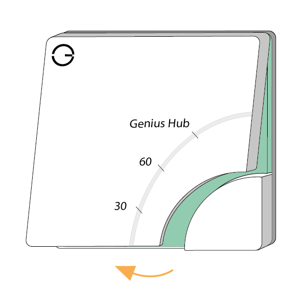
The first component to be installed is the Genius Hub. This is the ‘brains’ of the system, which communicates with all of the other devices and allows you to control your heating remotely.
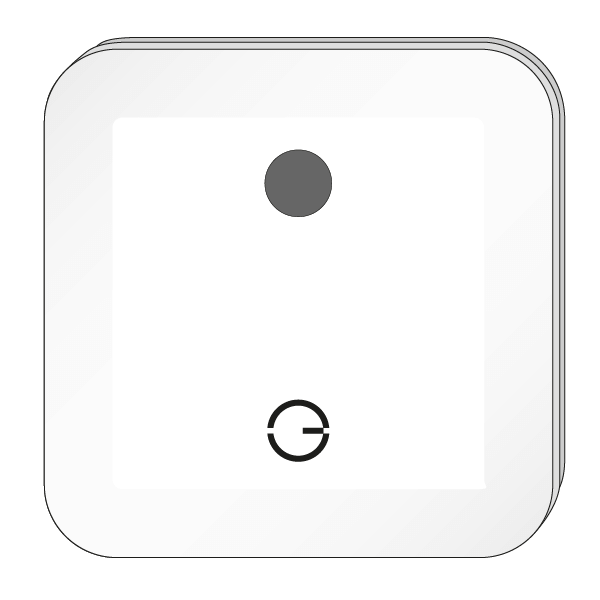
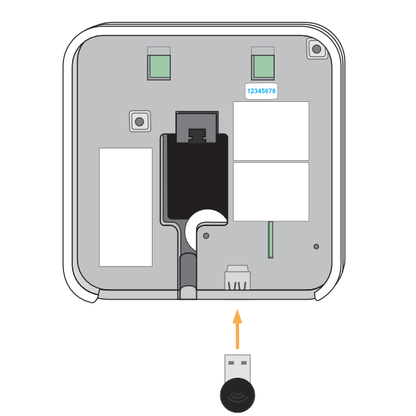
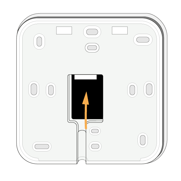
The Genius Hub can be placed flat on a surface, such as a cabinet or mounted on a wall. To mount it onto a wall, first remove the back plate by turning the Genius Hub around so the logo is facing away from you with the cutout for the Ethernet cable (see point 3) at the bottom. Slide the segmented back plate in the centre of the Genius Hub down, holding the outside of the Genius Hub. Once it has moved approximately 1 cm down, it can be pulled away from the Genius Hub. The back plate can be screwed to the wall with the segmented part facing the wall. Make note of the 8 blue characters for the Registration.
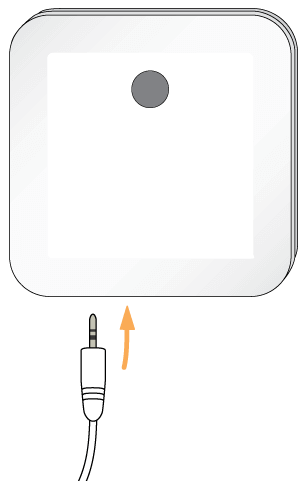
Before you screw the backplate to the wall, place the Ethernet Cable through the cutout so it is between the backplate and the wall.
The Genius system has been tested with a wide variety of boilers, heat pumps and other heat sources and these are controlled by the use of the Electric Switch(es).
The Electric Switch should be wired into the same fused spur as the relevant zone valve or immersion heater.
In normal operation, there will be no lights when the unit is not heating and one or more red
lights near the button when heating.
Combination Boiler (one Electric Switch)
For control of a single Heating zone, such as a combination (combi) boiler, a single electric Switch is required. This will be wired either to the ‘Call for Heat’ terminals or boiler wiring centre as appropriate.
Note: If there is no existing boiler programmer then the Electric Switch(es) must be wired into the boiler as if it were an external programmer or thermostat. See the wiring diagrams provided by the boiler manufacturer to confirm the wiring guides provided with this installation manual. If you remove an existing wired house thermostat from the control circuit, it must also be removed from the control in the boiler wiring centre, otherwise the Electric Switch will not have control over the boiler.
System Boiler (multiple Electric Switches)
For a system boiler, at least Electric Switches will be required. One for each zone of heating, such as one for the Central Heating and one for the Hot Water. Extras may be required if there are multiple Central Heating zones, or multiple heating types as wet underfloor heating is also present. These will most likely be wired to the zone valve(s).
Hot Water Time & Temperature Control (Electric Switch andTemperature Probe)
The Electric Switch and Temperature Probe is used to measure the temperature of the Hot Water Tank. The Electric Switch must be wired into a switched, fused spur near the Hot Water tank. Place the end end of the Temperature Probe into the pocket/under the insulation of the hot water tank. The Electric Switch and Temperature Probe, which is used to measure the temperature of the Hot WaterTank. The Electric Switch must be wired into a switched, fused spur near the hot water tank. Place the end for the Temperature Probe into the pocket/under the insulation of the hot water tank
If the Hot Water Tank has an immersion heater backup, this can be wired into the electric Switch (output) so you can also control the heating of the hot water from the immersion heater as well as the boiler.
NOTE: At no point should the Temperature Probe be pulled out or removed from the electric Switch.
The Electric Switch should be wired into the same fused spur as the relevant zone valve or immersion heater.
In normal operation, there will be no lights when the unit is not heating and one or more red lights near the button when heating.
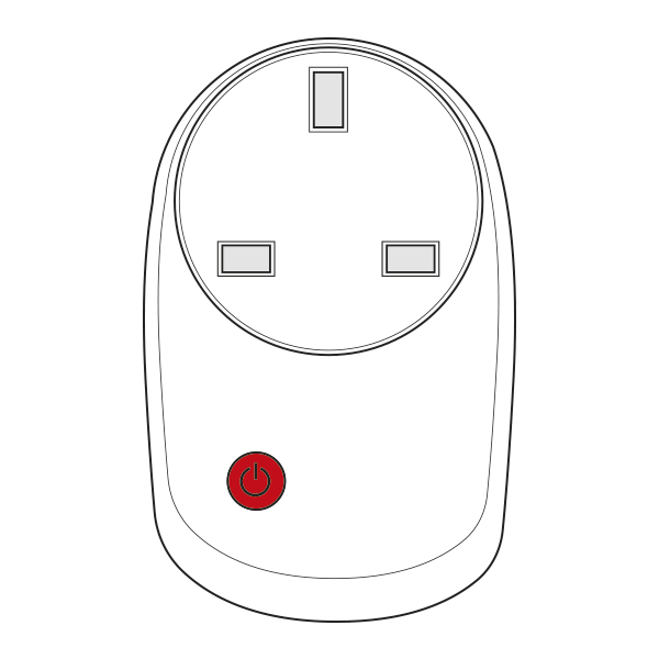
Smart Plugs can be used for 2 different purposes. They can be controlled via the app to switch devices plugged into them, via a schedule. They will boost the signal around the property improving reliability of the system and battery life.
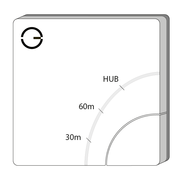
The signal travels in straight lines and the only devices that relay the messages are the Smart Plugs, Electric Switches and the Receiver Units. The signal does not bend or bounce, so when positioning think about how thick the wall is that the signal is going to have to pass through to get back to the Genius Hub. Consider that thick stone or concrete walls may be difficult for the wireless signal to penetrate, so the Smart Plug may need to be positioned in a wall socket, which gives a longer route but through thinner walls.
For the Genius Radiator Valves, the Genius Smart Plug (Dual Band) is the only device which relay the messages, and so should be spread throughout the property between the Genius Hub and any Genius Radiator Valves.
If you are using the Smart Plugs to boost the signal, they are often placed in one of 2 configurations:
Do not plug anything into a Smart Plug which needs to remain on all of the time such as a fridge or freezer. The Smart Plugs may intermittently turn off, causing anything that you plug into it to also turn off.
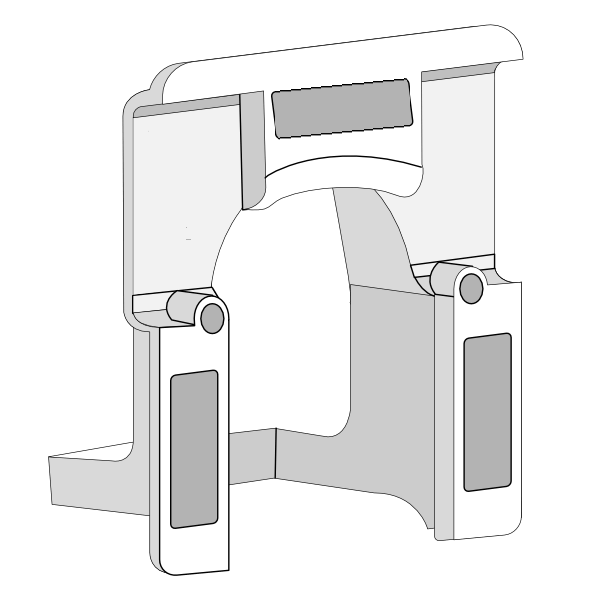
Installing the PlugLock
The PlugLock is used in HMOs and commercial buildings as a tamper-proof option for the Genius Smart Plug.
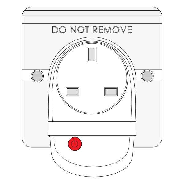
There are 2 ways to install the PlugLock with either the Smart Plug (Single Band) or Smart Plug (Dual Band):
The Genius Hub system uses a radio protocol called Z-Wave and Zigbee* which creates a wireless network (separate from WiFi) around your home. The network is low-powered, as most of the devices are battery-powered and this helps to conserve battery life.
All of the devices on the network communicate with the Hub – this is the ‘brain’ of the network and it tells the heating system what to do. The Hub does this by sending ‘messages’ to the device that it wishes to control.
If two devices are placed far away from each other, or there is a lot of material separating two devices (i.e. thick stone walls for example), then the radio signal may not be strong enough for those devices to communicate well.
For further on the Positioning Guidelines and scenarios please see here: https://geniushub.atlassian.net/wiki/x/U6kg
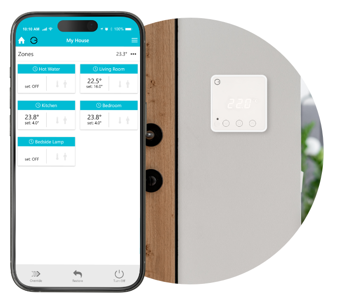
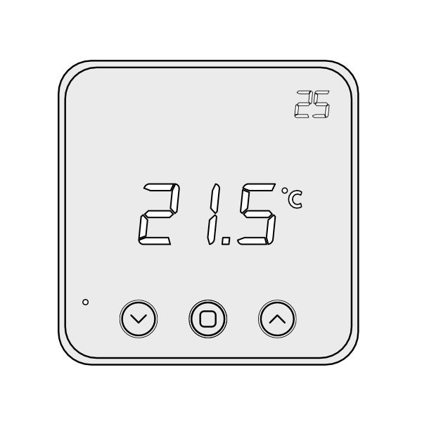
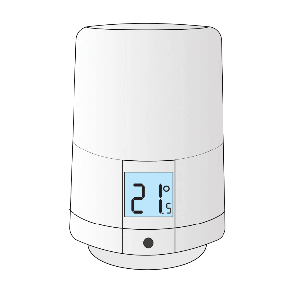
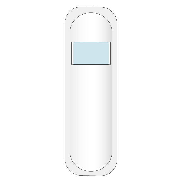
The thermostat provides you with an easy way to see the temperature in the room as well as a quick way of overriding the temperature without loading the app.
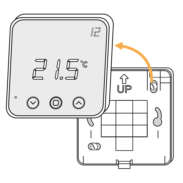
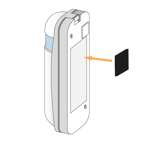
1. First, remove the Room Thermostat from its backplate using a flat bladed screwdriver and placing this in the cutout in the underside of the device, before levering the front away.
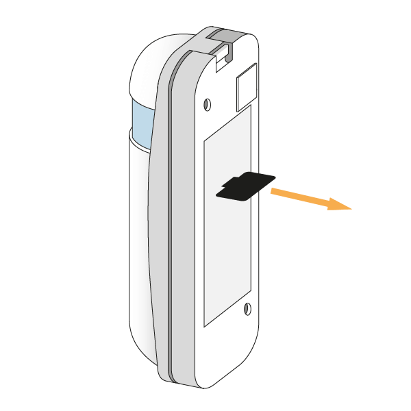
2. Turn the Room Thermostat over, so the screen is facing away from you and pull out the plastic tab to connect the battery.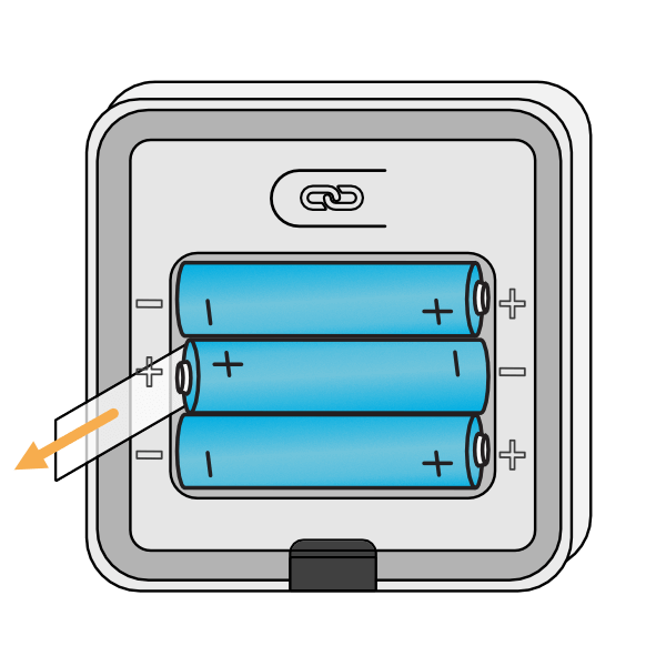
3. Affix the backplate to the wall, with the up arrow at the top.
The golden rules for positioning a Room Thermostat are:
4. First screw the backplate to the wall in the chosen room. Then fit the Room Thermostat onto the backplate by aligning it at the top and rotating it down to meet at the bottom.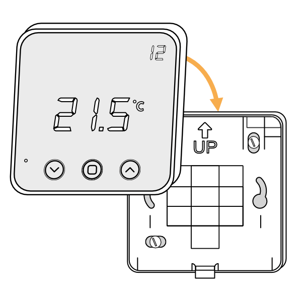
The Radiator Valves easily replace the majority of existing TRVs to give you the ability to schedule each room independently, without any plumbing being required.
Each Radiator Valve comes with two adapters. The two adapters fit the Radiator Valve onto either an M30x1.5mm thread (the UK standard which fits most brands of TRV) or a Danfoss RA fitting (the adapter with the grub screw). To mount the Radiator Valve:
Remove the existing TRV head (this is the part which turns and normally has the number 1-5 on it to regulate the temperature) from the radiator. Usually this requires loosening a nut between the TRV head and the valve body (the part the water flows through). Fasten the new adapter to the TRV body on the radiator. Screw the adapter down onto the TRV body if using the M30 x 1.5mm adapter, or attach the RA adapter & valve onto the radiator & tighten up the grub screw using a 2mm hex (Allen) key. The image below shows the M30 adapter being fitted.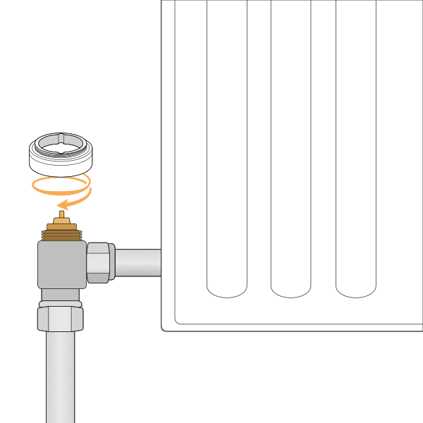
If using the Danfoss RA adapter make sure that the grub screw is done up very tight as the adapters can work loose over time, which stops the Radiator Valve being able to shut off the flow of water to the radiator, causing the radiator to heat up when it is supposed to be off.
Remove the battery cover by depressing the tab at the back of the valve, and pull the cover up and away from the valve.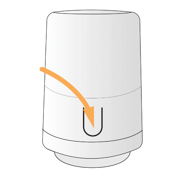
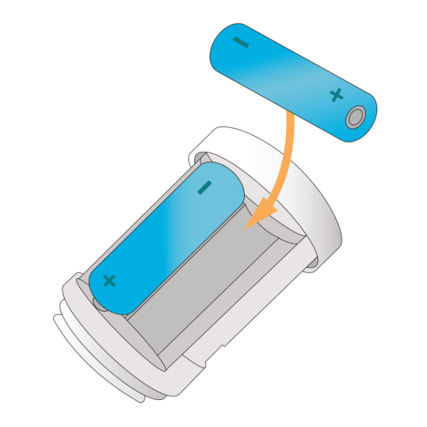
Place 2 x AA batteries in the valve, a temperature should appear on the screen.
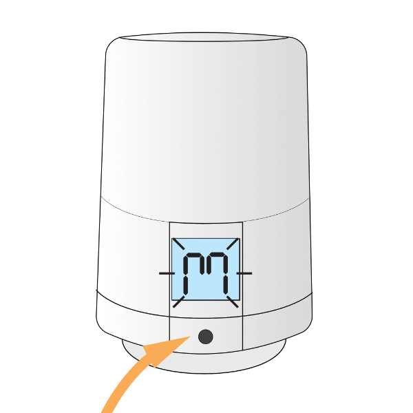
Press and hold the button for 3 seconds until an ‘M’ appears on the screen. The ‘M’ will begin to flash on the screen, the valve will buzz and the plunger in the underside of the valve will retract. The valve is now in Mount Mode.
The Valve must be in mount mode when being attached to the radiator.
Screw the valve down onto the adapter. 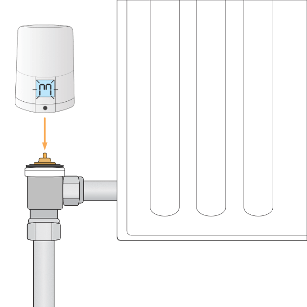
Press and hold the button for 3 seconds until the valve starts to buzz and a temperature appears on the screen. This takes the valve out of Mount Mode.
The Radiator Valve learns the characteristics of the radiator and room for the first couple weeks of heating after installation. This can cause it to be slow to heat up during this period. For more information on this process see: https://docs.geniushub.co.uk/x/T4BoBg
You can stop a valve from learning if you simply press any button on the valve or turning the case whilst it is trying to warm up the room. The valve abandons the learning for that time and will wait until the next time it is called to heat a room before it tries to learn again.
If you put a valve into ‘mount mode’ again then it will starting the learning process again.
The Room Sensors report a more accurate temperature to the app as they are installed at chest height and away from heat sources. They can also detect motion in the property to give you access to Sense and Footprint Mode for each zone.
Often the best position for a room sensors in on an internal wall and next to a light switch.
The Motion Sensors report when movement is detected in a room, providing access to Sense and Footprint Mode in the app and allowing the heating to only heat when a room is in use.
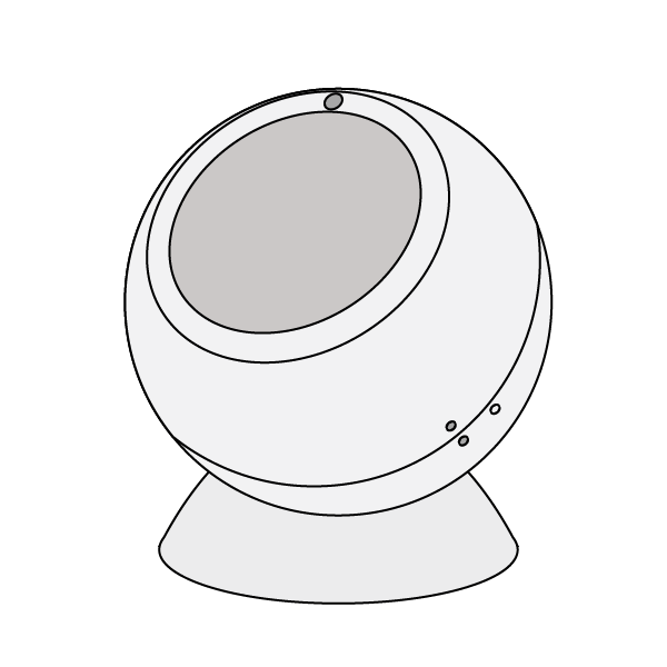
1. First, fit the round, concave mount to the surface you want to attach the Motion Sensor to, as the Motion Sensor can be rotated on the mount, it can be placed on nearly any flat surface including walls and ceilings. As the Motion Sensor does not measure the temperature, it can be placed at any height and it does not matter if it is near a heat source in the room.
2. Open the Motion Sensor by twisting the 2 halves until the solid and hollow dots line up, then pull the back off the Motion Sensor.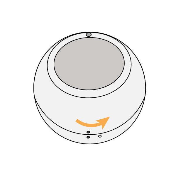
3. Pull out the battery tab, then replace the back cover with the hollow dot and solid dots lining up. Twist the back cover until the 2 solid dots line up once again.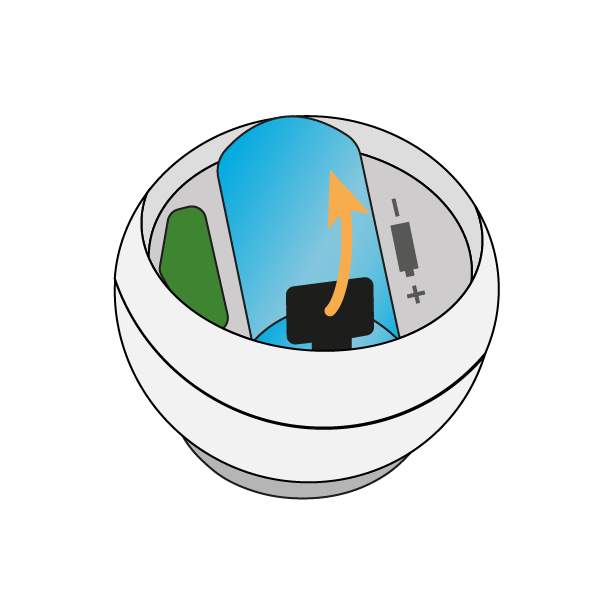
4. Place the Motion Sensor on the mount. The 2 parts fasten together via magnetism allowing you to rotate the Motion Sensor to face the part of the room people are going to occupy.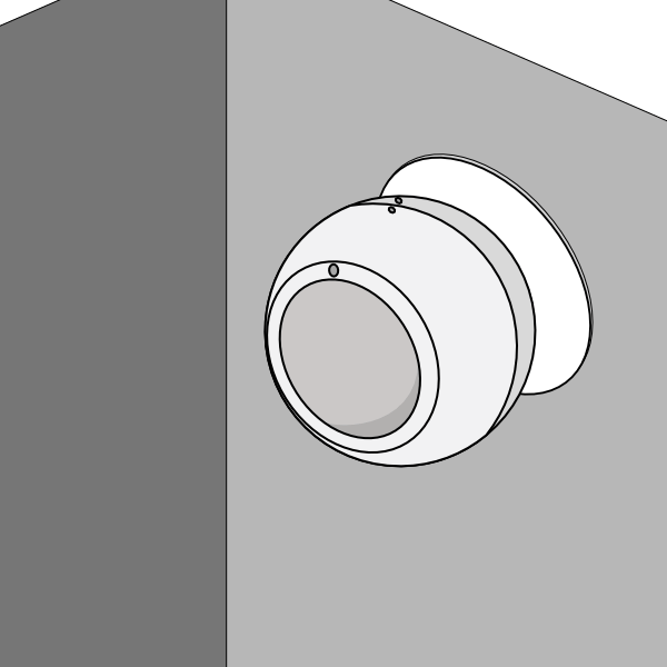
Remember to leave the pack of fixings behind with the customer in case they want to move the Motion Sensor at a later date.